Wednesday, January 28, 2015


Thursday, November 20, 2014
How a single phase motor is similar to 3 phase motor?
A single phase induction motor is very similar to a 3-phase squirrel cage induction motor. It has
(i) a squirrel-cage rotor identical to a 3-phase motor
(ii) a single-phase winding on the stator
What is major difference between a 3-phase induction motor and a single-phase induction motor?
Why single phase induction motor does not self starts?
What is basic method to start single phase induction motor and why it is not preferred?
A single phase induction motor is very similar to a 3-phase squirrel cage induction motor. It has
(i) a squirrel-cage rotor identical to a 3-phase motor
(ii) a single-phase winding on the stator
What is major difference between a 3-phase induction motor and a single-phase induction motor?
Unlike a 3-phase induction motor, a single-phase induction motor is not self- starting but requires some starting means.
Why single phase induction motor does not self starts?
The single-phase stator winding produces a magnetic field that pulsates in strength in a sinusoidal manner. The field polarity reverses after each half cycle but the field does not rotate. Consequently, the alternating flux cannot produce rotation in a stationary squirrel-cage rotor.
What is basic method to start single phase induction motor and why it is not preferred?
If the rotor of a single-phase motor is rotated in one direction by some mechanical means, it will continue to run in the direction of rotation. As a matter of fact, the rotor quickly accelerates until it reaches a speed slightly below the synchronous speed. Once the motor is running at this speed, it will continue to rotate even though single-phase current is flowing through the stator winding. This method of starting is generally not convenient for large motors. Nor can it be employed fur a motor located at some inaccessible spot.
Tuesday, November 18, 2014
Why Power Plant Capacity Rated in MW and not in MVA?
In a Generating station, the prime mover (Turbine) generates only and only Active Power. That’s why we rated a power plant capacity in MW instead of MVA. Its mean no matter how large your generator is, but it depends on the capacity of the engine (Prime mover/Turbine) I.e. a 50MW turbine connected to a 90MVA alternator in a power plant will generate only 50MW at full load. In short, a power plant rating is specified in terms of prime mover /Turbine (Turbine rating may be seen by nameplate rating which is in MW or Horsepower (HP) not in MVA) and not by the alternator set coupled to it.
Another thing is that, electric power company charges their consumer for kVA while they generate kW (or MW) at the power station (Power plant).They penalize their consumer for low Power factor because they are not responsible for low power factor and kVA but you. Moreover, in power plant, power factor is 1 therefore MW is equal to MVA …… (MW = MVA x P.f).
Why A.C needs more insulation than D.C at same voltage level?
For the same working voltage, the potential stress on the insulation is less than in case of DC system than that AC system. therefore , a DC line require less insulation.In other words A DC System has a less potential stress over AC system for same Voltage level, this is why AC needs more insulation over DC system.
Thursday, November 13, 2014
Comparison between Star (Y) and Delta (Δ) Connections
Star (Y) Connection
|
Delta (Δ) Connection
|
In STAR connection, the starting or finishing ends (Similar ends) of three coils are connected together to form the neutral point. A common wire is taken out from the neutral point which is called Neutral.
|
In DELTA connection, the opposite ends of three coils are connected together. In other words, the end of each coil is connected with the start of another coil, and three wires are taken out from the coil joints
|
There is a Neutral or Star Point
|
No Neutral Point in Delta Connection
|
Three phase four wire system is derived from Star Connections (3-Phase, 4 Wires System) We may Also derived 3 Phase 3 Wire System from Star Connection
|
Three phase three wire system is derived from Delta Connections (3-Phase, 3 Wires System)
|
Line Current is Equal to Phase Current. i.e.
Line Current = Phase Current
IL = IPH
|
Line Voltage is Equal to Phase Voltage. i.e.
Line Voltage = Phase Voltage
VL = VPH
|
Line Voltage is √3 times of Phase Voltage. i.e.
VL = √3 VPH
|
Line Current is √3 times of Phase Current. i.e.
IL = √3 IPH
|
The Total Power of three phases could be found by
P = √3 x VL x IL x CosФ …. Or
P = 3 x VPH x IPH x CosФ
|
The Total Power of three phases could be found by
P = √3 x VL x IL x CosФ … or
P = 3 x VPH x IPH x CosФ
|
The speeds of Star connected motors are slow as they receive 1/√3 voltage.
|
The speeds of Delta connected motors are high because each phase gets the total of line voltage
|
In Star Connection, the phase voltage is low as 1/√3 of the line voltage, so, it needs low number of turns, hence, saving in copper.
|
In Delta connection, The phase voltage is equal to the line voltage, hence, it needs more number of turns.
|
Low insulation required as phase voltage is low
|
Heavy insulation required as Phase voltage = Line Voltage.
|
In Power Transmission, Star Connection system is general and typical to be used.
|
In Power Distribution and industries, Delta Connection is general and typical to be used.
|
Wednesday, November 12, 2014
(1) Real Power: (P)
Alternative words used for Real Power (Actual Power, True Power, Watt-full Power, Useful Power, Real Power, and Active Power)
In a DC Circuit, power supply to the DC load is simply the product of Voltage across the load and Current flowing through it i.e., P = V I. because in DC Circuits, there is no concept of phase angle between current and voltage. In other words, there is no Power factor in DC Circuits.
But the situation is Sinusoidal or AC Circuits is more complex because of phase difference between Current and Voltage. Therefore average value of power (Real Power) is P = VI Cosθ is in fact supplied to the load.
In AC circuits, When circuit is pure resistive, then the same formula used for power as used in DC as P = V I.
You may also read about Power Formulas in DC, AC Single Phase and and AC Three Phase Circuits.
Real Power formulas:
P = V I (In DC circuits)
P = VI Cosθ (in Single phase AC Circuits)
P = √3 VL IL Cosθ or (in Three Phase AC Circuits)
P = 3 VPh IPh Cosθ
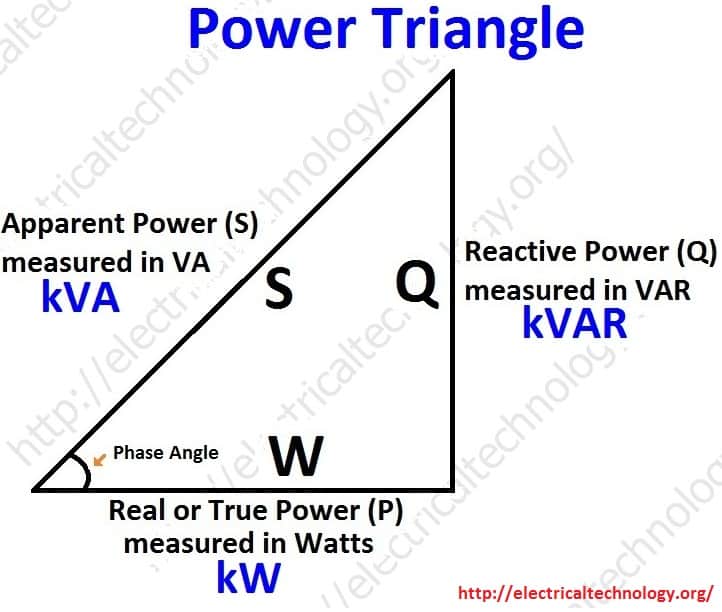
P = √ (S2 – Q2)or
P =√ (VA2 – VAR2) or
Real or True power = √ (Apparent Power2– Reactive Power2) or
kW = √ (kVA2 – kVAR2)
(2) Reactive Power: (Q)
Also known as (Use-less Power, Watt less Power)
The powers that continuously bounce back and forth between source and load is known as reactive Power (Q)
Power merely absorbed and returned in load due to its reactive properties is referred to as reactive power
The unit of Active or Real power is Watt where 1W = 1V x 1 A.
Reactive power represent that the energy is first stored and then released in the form of magnetic field or electrostatic field in case of inductor and capacitor respectively.
Reactive power is given by Q = V I Sinθ which can be positive (+ve) for inductive, negative (-Ve) for capacitive load.
The unit of reactive power is Volt-Ampere reactive. I.e. VAR where 1 VAR = 1V x 1A.
In more simple words, in Inductor or Capacitor, how much magnetic or electric field made by 1A x 1V is called the unit of reactive power.
Reactive power formulas:
Q = V I Sinθ
Reactive Power=√ (Apparent Power2- True power2)
VAR =√ (VA2 – P2)
kVAR = √ (kVA2 – kW2)
(3) Apparent Power: (S)
The product of voltage and current if and only if the phase angle differences between current and voltage are ignored.
Total power in an AC circuit, both dissipated and absorbed/returned is referred to asapparent power
The combination of reactive power and true power is called apparent power
In an AC circuit, the product of the r.m.s voltage and the r.m.s current is calledapparent power.
It is the product of Voltage and Current without phase angle
The unit of Apparent power (S) VA i.e. 1VA = 1V x 1A.
When the circuit is pure resistive, then apparent power is equal to real or true power, but in inductive or capacitive circuit, (when Reactances exist) then apparent power is greater than real or true power.
Apparent power formulas:
S = V I
Apparent Power = √ (True power2 + Reactive Power2)
kVA = √kW2 + kVAR2
AlsoNote that;
Resistor absorbs the real power and dissipates in the form of heat and light.
Inductor absorbs the reactive power and dissipates in the form of magnetic field
Capacitor absorbs the reactive power and dissipates in the form of electric or electrostatic filed

Alternative words used for Real Power (Actual Power, True Power, Watt-full Power, Useful Power, Real Power, and Active Power)
In a DC Circuit, power supply to the DC load is simply the product of Voltage across the load and Current flowing through it i.e., P = V I. because in DC Circuits, there is no concept of phase angle between current and voltage. In other words, there is no Power factor in DC Circuits.
But the situation is Sinusoidal or AC Circuits is more complex because of phase difference between Current and Voltage. Therefore average value of power (Real Power) is P = VI Cosθ is in fact supplied to the load.
In AC circuits, When circuit is pure resistive, then the same formula used for power as used in DC as P = V I.
You may also read about Power Formulas in DC, AC Single Phase and and AC Three Phase Circuits.
Real Power formulas:
P = V I (In DC circuits)
P = VI Cosθ (in Single phase AC Circuits)
P = √3 VL IL Cosθ or (in Three Phase AC Circuits)
P = 3 VPh IPh Cosθ
P = √ (S2 – Q2)or
P =√ (VA2 – VAR2) or
Real or True power = √ (Apparent Power2– Reactive Power2) or
kW = √ (kVA2 – kVAR2)
(2) Reactive Power: (Q)
Also known as (Use-less Power, Watt less Power)
The powers that continuously bounce back and forth between source and load is known as reactive Power (Q)
Power merely absorbed and returned in load due to its reactive properties is referred to as reactive power
The unit of Active or Real power is Watt where 1W = 1V x 1 A.
Reactive power represent that the energy is first stored and then released in the form of magnetic field or electrostatic field in case of inductor and capacitor respectively.
Reactive power is given by Q = V I Sinθ which can be positive (+ve) for inductive, negative (-Ve) for capacitive load.
The unit of reactive power is Volt-Ampere reactive. I.e. VAR where 1 VAR = 1V x 1A.
In more simple words, in Inductor or Capacitor, how much magnetic or electric field made by 1A x 1V is called the unit of reactive power.
Reactive power formulas:
Q = V I Sinθ
Reactive Power=√ (Apparent Power2- True power2)
VAR =√ (VA2 – P2)
kVAR = √ (kVA2 – kW2)
(3) Apparent Power: (S)
The product of voltage and current if and only if the phase angle differences between current and voltage are ignored.
Total power in an AC circuit, both dissipated and absorbed/returned is referred to asapparent power
The combination of reactive power and true power is called apparent power
In an AC circuit, the product of the r.m.s voltage and the r.m.s current is calledapparent power.
It is the product of Voltage and Current without phase angle
The unit of Apparent power (S) VA i.e. 1VA = 1V x 1A.
When the circuit is pure resistive, then apparent power is equal to real or true power, but in inductive or capacitive circuit, (when Reactances exist) then apparent power is greater than real or true power.
Apparent power formulas:
S = V I
Apparent Power = √ (True power2 + Reactive Power2)
kVA = √kW2 + kVAR2
AlsoNote that;
Resistor absorbs the real power and dissipates in the form of heat and light.
Inductor absorbs the reactive power and dissipates in the form of magnetic field
Capacitor absorbs the reactive power and dissipates in the form of electric or electrostatic filed
Subscribe to:
Posts (Atom)